TL431 Analysis and Simulation
By Shuo Chen (chenshuo_at_chenshuo.com)
Latest version: https://chenshuo.github.io/notes/tl431/
Comments and discussions: https://github.com/chenshuo/notes/discussions
Series of analysis & simulation of IC regulator designed in 1970s:
In this post, transistor = BJT, however, base currents are ignored by default.
Bandgap voltage reference
See "How a bandgap reference works" section in https://www.righto.com/2014/09/reverse-engineering-counterfeit-7805.html
The thermal voltage is proportional to absolute temperature (PTAT). at room temperature (27°C, or 300K).
Ref. https://en.wikipedia.org/wiki/Boltzmann_constant#The_thermal_voltage
has a positive temperature coefficient of about 86.2μV/°C.
Therefore, we usually need to cancel out the tempco of one , which normally has a negative tempco about -2mV/°C.
The actual tempco of is related to itself, its first order approximation is , see formula in https://en.wikipedia.org/wiki/Silicon_bandgap_temperature_sensor
Ebers–Moll model: , equivalently .
Reverse saturation current is directly proportional to the emitter-base junction area of a transistor, which we just call the area of the transistor.
If we set different emitter currents of two transistors, we will get two different , their difference is called , . is current density, directly proportional to emitter current , inversely proportional to its area.
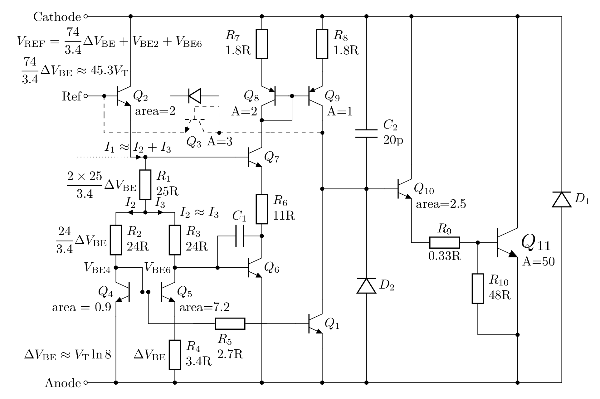
The internal schematic
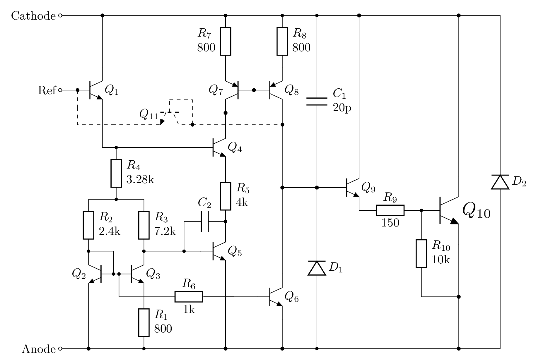
Resistor values are taken from official TI datasheet https://www.ti.com/lit/ds/symlink/tl431.pdf.
The resistor and transistor numbering follows SPICE model by Eugene Dvoskin.
Transistor is drawn in dashed lines, as it is off in normal operation mode.
IIUC, it acts like a diode to shutdown the output when Ref is connected to Anode.
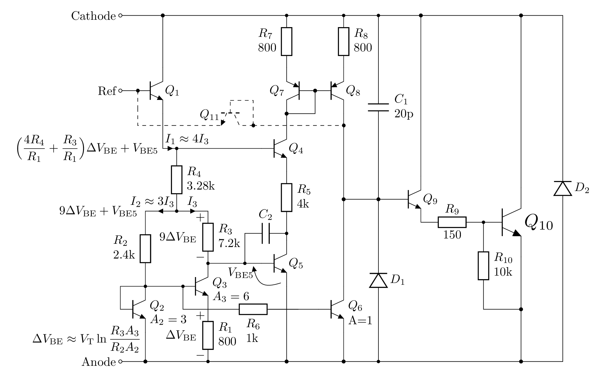
Analysis
Ignoring base currents, assuming . As we will see in the next section , we can actually estimate that .
For the following analysis, we assume area ratio of being , taken from The TL431 in loop control by Christophe Basso. Eugene Dvoskin's SPICE model (at the end of this page) uses a different ratio () though.
To show a larger image, right click and then "Open image in new tab".
- There are 11 transistors in total, is normally off, so we need to analyze 10 BJTs only.
- It's easy to see that and form a Darlinton pair, it's the output stage.
- It's also easy to recognize that and is a current mirror, if we assuming they have the same area. (In Ken Shirriff's schematic below, their areas are different, though.)
- The rest of 6 transistors are tangled together, let's analyze them in parts.
Notation:
- denotes the Base-Emitter junction voltage of transistor
- denotes the base voltage of transistor .
- denotes the emitter voltage of transistor , which is also known as .
- It's obvious from the schematic above, .
- denotes the base current of transistor , which equals to currents on , .
- denotes the voltage across resistor , which is , assuming .
- , , are currents on , , , respectively, as shown in the full schematic above.
- Ignoring base currents, , , .
Calculation
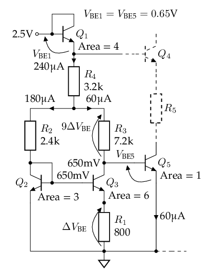
Reference voltage
The reference voltage can be divided into 4 segments, from base of to ground: .
First, we consider and resistors connected to them, it's easy to find .
-
Assuming , .
-
, so .
- mV, given that the area of is of .
- , assuming .
- The current on is , so
- Sum of voltages across and is V.
- Tempco of is = 3.922 mV/°C, canceling out negative tempco of , which is
- In theory, when its tempco is zero.
is critical, it controls both and its tempco, I guess that's why it shows 3 decimal places in the datasheet (3.28kΩ), while other resistors has only 2.
Estimating for fun. It's rough estimation, so we use rounded values, like 1.2V, instead of 1.174V for .
- Assuming V for now.
- Sum of voltages across and is
- The total resistance across the aforementioned 1.2V is kΩ
- The current on is mA, so μA,
- The current on is , so μA, and μA.
- The datasheet says typical μA, so we estimate .
The voltages and currents shown in above schematic are from SPICE simulation.
Error amplifier
Second, we add into the picture, omitting and for now.
It's safe to assume that all share the same (emitter) current, because and form a current mirror, and it sets the currents of , , and to be all the same.
We will show that the current is 60μA for , same as emitter current of .
- , because is less than 1μA, so voltage drop on is less than 1mV.
- Area of is 1E, area of is 3E, with the same base voltage,
- We already knew that , so μA. In other words, has same current as .
- Due to current mirror made of and , and mirrors the current of . (But, see the note below.)
- In conclusion, 6 transistors all have the same current as , when balanced, that is μA.
Although this conclusion matches the simulation of the next section, there is an unsolved puzzle: the current mirror of and is supposed to copy 's current to , but not vice versa. However, the analysis above assume current of , , is set by , then mirrored in and . Is this reasonable? My explanation is that the feedback of output stage will bring the circuit into the balanced state, where . ()
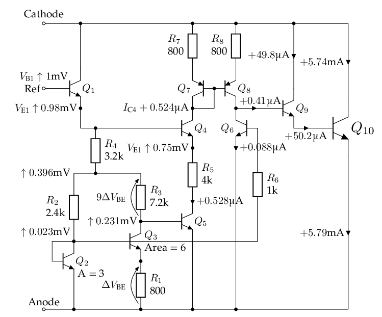
The following diagram shows what we have analyzed so far.
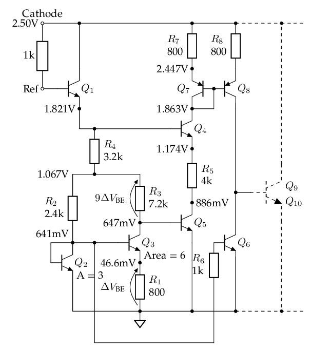
The voltages and currents shown in above schematic are from SPICE simulation.
Tempco
Recall that .
-
-
-
Tempco of is = 3.922 mV/°C
-
Tempco of is mV/°C
-
Tempco of mV/°C
From this calculation, we concluded that TL431's reference voltage will change 20.44mV when temperature changes from 0°C to 70°C. However TL431 datasheet says it will only change 4mV in this case, which is 5x better than our calculation.
I don't know how does TL431 archive such good tempco when , because tempco of is determined only by itself: mV/°C. Unless the chip manufacturer managed to change .
Third, let's calculate the required , just for fun.
Recall that V, in order to get V, we need V.
There are at least two ways to achieve that, given that :
- Area of is of , so V.
- μA
- fA, this is for
- for , its fA.
- Area of is the same as ,
so mV.
- mV, mV
- fA
- for , its fA.
 second way to estimate .
In the SPICE model, we set fA for NPN transistors.
Feedback
Fourth, the feedback loop.
is an emitter follower, and is differential pair, current mirror and serves as active load, the error amplifier output is collector of , which feeds into base of .
If increases a tiny bit, we want to increase collector current of by a lot (a few mA per mV), to hopefully bring back to its nominal value (2.495V) through the external feedback network (usually two resistors).
The following diagram shows what will happen if increases by 1mV.
Explanation:
- As , , it drains more current from . Because mirrors , so .
- is almost linear with , because .
- and form a current source,
- In short, , while
- only goes up linear with , much lower than , the increase of mostly feeds into base of .
- is amplified by and , increase a lot.
- The increase of sink current will hopefully bring down back.
Simulation
Simulating the following circuit using NgSpice in Python Jupyter.
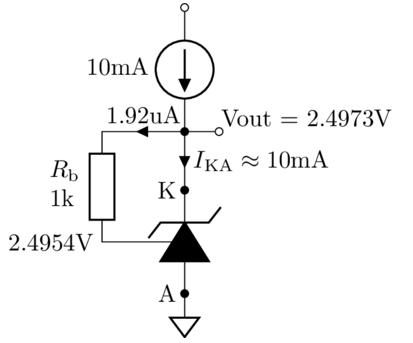
SPICE netlist and results are in https://github.com/chenshuo/notes/blob/master/notebooks/TL431.ipynb, view in Google Colab.
To show a larger image, right click and then "Open image in new tab".
Dynamic Impedance
If we sweep the bias current from 1mA to 100mA, then measure the the output voltage range, we will get the output impedance of this circuit .
It's 0.14Ω from simulation, lower than 0.2Ω as stated in the datasheet.
DC Gain
It's about 61dB from simulation, higher than 55dB as stated in TI's datasheet.
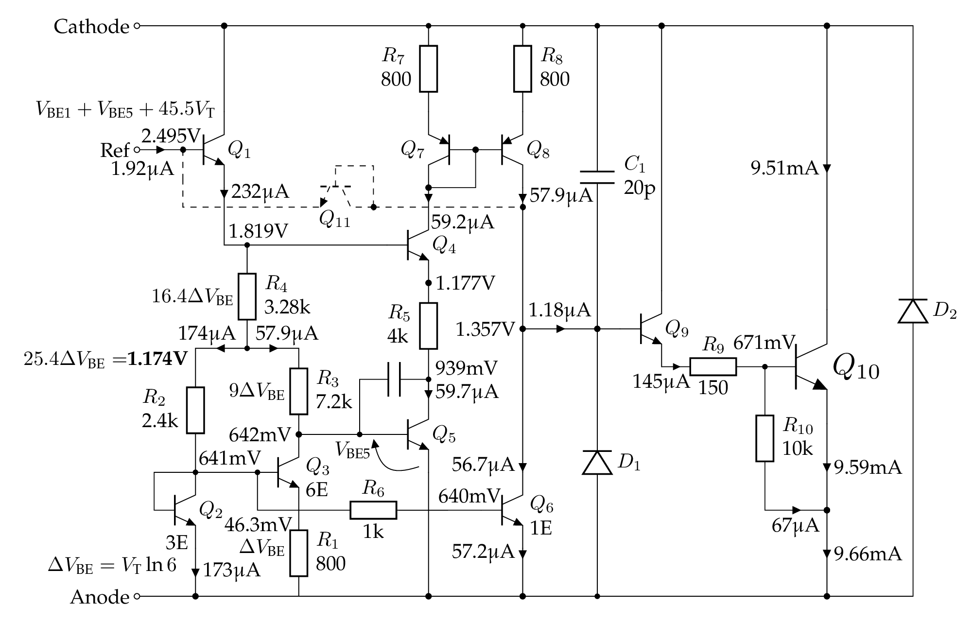
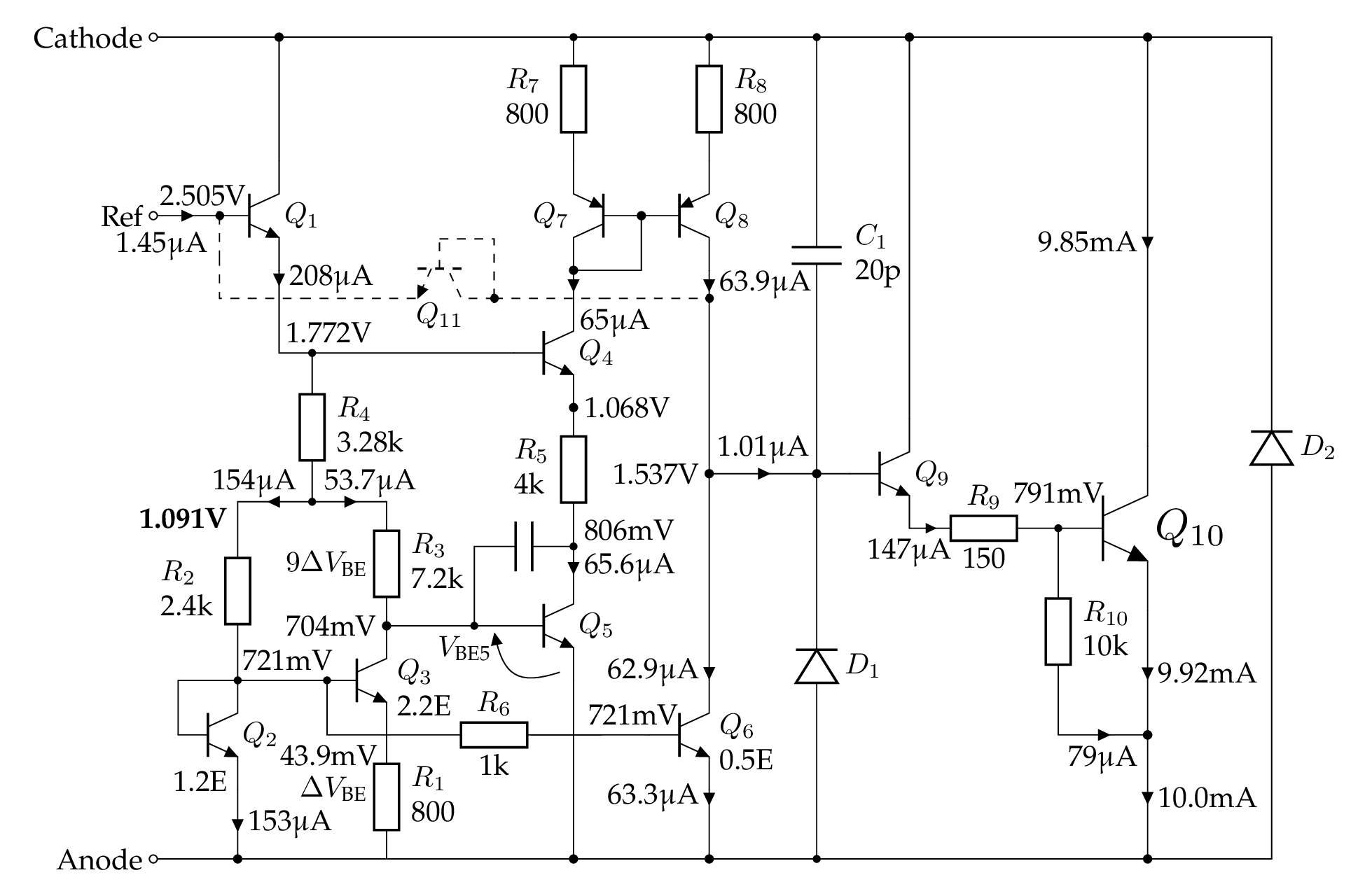
Another schematic by Ken Shirriff
https://www.righto.com/2014/05/reverse-engineering-tl431-most-common.html
The resistances on the official schematic above are very different from what can be seen from the die.
Note: the transistor and resistor numbers in the following schematic match Ken Shirriff's post, don't be confused with results above.
To show a larger image, right click and then "Open image in new tab".
Here's brief analysis of its DC operating point, ignoring base currents.
- Assuming
- Voltage drops on and are approx the same. and , so .
-
The area ratio of and is , so voltage on is at room temperature.
-
Assuming for , its , so voltage on is
-
Voltage on is .
-
In total,
-
The PTAT portion , which should be in right amount to cancel tempco of two .
-
Assuming , so that μA. With μA, we have .
- ,
-
TODO: analyze the current mirror of gain 0.5, made of and .
SPICE model by Eugene Dvoskin
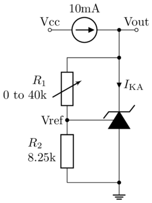
Simulating the following circuit using NgSpice in Python Jupyter.
https://github.com/chenshuo/notes/blob/master/notebooks/AnalogCircuits.ipynb, view in Google Colab.
Scroll down to "TL431 Regulator" section.
The Vref can be tuned to 2.495V by changing R4 to 3.22kΩ.
μA kΩ